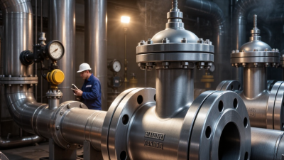
Choosing a hydraulic rotary actuator in 2026 requires more than comparing torque figures online. The correct choice begins with the machine’s real working conditions.
Dr. Ian Watton, a respected hydraulic systems author and educator, states, “An actuator must be selected as part of the complete system, not in isolation.” That principle remains practical. A forestry attachment, for example, may face shock loads, muddy seals, restricted space, and sudden directional changes. A factory indexing table may require different priorities, including repeatable angle control, low leakage, and quiet operation.
This guide examines the details that often decide performance. We will compare rated torque, starting torque, operating pressure, rotation angle, speed, mounting style, and shaft capacity. Port size also matters. A small port can restrict flow and slow the actuator, even when the pump appears powerful enough. Duty cycle deserves attention too. Continuous rotation and occasional 90-degree movement create very different thermal demands.
Reliable selection also depends on evidence. Review manufacturer test data, pressure ratings, seal materials, corrosion protection, and published tolerances. Ask how the actuator behaves under side loading, not only under ideal laboratory conditions. Confirm compatibility with the hydraulic fluid and the surrounding temperature range.
There is no perfect catalog answer.
Some specifications remain incomplete. Real machines introduce vibration, contamination, and operator habits that brochures cannot fully predict. Therefore, engineers should validate the selected hydraulic rotary actuator through load calculations, prototype testing, and service feedback. A modest safety margin is valuable, but excessive oversizing can reduce control quality, increase cost, and waste hydraulic energy.
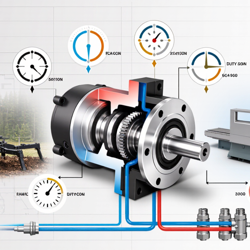
Choosing a hydraulic rotary actuator in 2026 starts with defining the operating requirements. Do not begin with torque alone. Record the driven load, rotation angle, speed, cycle frequency, and available pressure. Measure the real cycle. A 90-degree movement every 20 seconds creates different demands than continuous oscillation.
Calculate breakaway torque, running torque, and acceleration torque separately. Include friction, shock loads, gravity, and process changes. Then specify the maximum pressure, return-line pressure, fluid type, temperature range, and acceptable leakage. ISO 4413 emphasizes risk reduction, pressure control, and safe energy isolation in hydraulic systems. These requirements should shape the actuator and its control valves.
The installation environment matters just as much. Dust, washdown water, salt, vibration, and poor filtration can shorten service life. A 2024 Grand View Research analysis valued the global hydraulic equipment market at more than USD 49 billion in 2023, showing the scale of equipment used across demanding industries. Meanwhile, IFR’s World Robotics 2024 report recorded 541,302 industrial robot installations in 2023. Automation is raising expectations for repeatability and diagnostic feedback. Specify position accuracy, sensor resolution, and fail-safe behavior before selecting a model. I would also test the actual load profile, not only the catalog rating. A spreadsheet can look complete and still miss heat buildup, pressure spikes, or mounting flex. That is where many selection decisions become expensive.
| Operating Requirement | Key Data to Define | Typical Engineering Range or Reference | Why It Matters | Recommended Selection Check |
|---|---|---|---|---|
| Required Torque | Continuous torque, peak or breakaway torque, external load torque, and safety factor | Define continuous and peak torque separately; a design safety factor of approximately 1.25–1.50 is commonly considered for known loads | Insufficient breakaway torque can prevent startup, while excessive oversizing may reduce controllability and increase cost | Select an actuator whose rated continuous and peak torque both exceed the calculated application requirements |
| Hydraulic Pressure | Normal operating pressure, maximum pressure, pressure spikes, and relief-valve setting | Many industrial hydraulic systems operate around 70–250 bar; some heavy-duty systems operate near 350 bar | Pressure directly affects available torque and determines the required housing, seals, shaft, and bearing strength | The actuator's continuous and peak pressure ratings must exceed actual system pressure, including transient spikes |
| Hydraulic Flow Rate | Minimum, nominal, and maximum flow in L/min; available pump flow; valve capacity | Small actuators may use a few L/min, while larger industrial units can require tens or hundreds of L/min | Flow controls rotational speed and influences pressure losses, heat generation, and valve sizing | Confirm that the actuator reaches the required speed at available flow without exceeding its maximum flow rating |
| Rotation Angle | Required angular travel, end-stop accuracy, repeatability, and need for continuous rotation | Quarter-turn applications commonly use 90°; other designs may require 180°, 270°, or a specified limited angle | Vane and rack-and-pinion actuators are generally selected for limited-angle motion, whereas continuous rotation requires a rotary motor design | Match the mechanical stop range and allowable overtravel to the valve, damper, gripper, or indexing mechanism |
| Rotational Speed | Required degrees per second, revolutions per minute, acceleration, and deceleration time | Specify speed at the actual operating pressure and flow; speed may drop under load because of leakage and pressure losses | High acceleration can create torque spikes, shock loads, vibration, and premature seal or bearing wear | Check rated speed, acceleration limits, cushioning options, and the control valve's metering capability |
| Torque and Speed Relationship | Required torque at each operating speed and duty point | Hydraulic power is approximately P = p × Q; mechanical output depends on volumetric and mechanical efficiency | An actuator may deliver high torque at low speed but require substantially more flow to maintain torque at higher speed | Review the complete torque-speed curve rather than selecting from torque or speed alone |
| Duty Cycle | Cycles per hour, operating time per cycle, rest time, and continuous or intermittent duty | State the duty as a percentage or as operating minutes per hour; 50% duty means approximately 30 operating minutes per hour | Duty cycle affects thermal loading, lubricant life, seal wear, and allowable continuous torque | Use continuous-duty ratings for applications that run without sufficient cooling or rest periods |
| Load Inertia | Moment of inertia, reflected gearbox inertia, angular acceleration, and stopping time | Calculate inertia in kg·m² and acceleration torque using T = J × α | High inertia can produce severe pressure spikes when the load starts, stops, or changes direction | Include acceleration and deceleration torque in the peak-load calculation and consider hydraulic cushioning |
| External Loads on the Shaft | Radial load, axial load, bending moment, overhung load, and coupling forces | Loads depend on shaft geometry and bearing arrangement; they must be checked against the actuator's published limits | External loads can damage bearings or seals even when the required driving torque is within rating | Use a separate support bearing or flexible coupling when external shaft loads exceed the actuator allowance |
| Positioning and Holding | Required angular accuracy, repeatability, drift tolerance, and holding time | Open-loop hydraulic positioning is affected by oil compressibility, leakage, valve resolution, and load variation | A hydraulic actuator alone may not provide precise long-term position holding under changing loads | Consider a counterbalance valve, pilot-operated check valve, mechanical lock, encoder, or closed-loop control when required |
| Hydraulic Fluid | Fluid type, viscosity range, cleanliness level, additives, and compatibility with seals | Common mineral hydraulic oils are often specified by ISO viscosity grades such as ISO VG 32, 46, or 68 | Incorrect viscosity or contaminated fluid can increase leakage, wear, temperature, and starting friction | Verify fluid and seal compatibility, and maintain the cleanliness level required by the complete hydraulic circuit |
| Operating Temperature | Minimum and maximum ambient temperature, oil temperature, start-up temperature, and heat dissipation | A common industrial oil-temperature target is approximately 30–60°C; the permitted range must be confirmed for the selected seals and fluid | High temperature accelerates seal aging and oil oxidation, while low temperature increases viscosity and starting torque | Check both actuator and hydraulic-fluid temperature limits under the worst-case duty cycle |
| Installation Environment | Dust, water exposure, salt spray, chemicals, outdoor use, vibration, and mounting orientation | Specify the required enclosure or corrosion-protection level according to the actual environment rather than using a generic rating | Environmental contamination can damage shaft seals, fasteners, coatings, and hydraulic connections | Confirm sealing, coating, drainage, mounting orientation, and hose protection requirements before final selection |
| Port and Plumbing Requirements | Port size, port standard, hose length, pipe diameter, valve type, and allowable pressure drop | Port sizing should support the required flow while limiting excessive velocity and pressure loss | Undersized lines can restrict speed, generate heat, and cause unstable motion or cavitation-related problems | Match ports and fittings to the circuit design and verify that return-line back pressure remains within the actuator limit |
| Cushioning and Shock Control | End-of-stroke speed, load inertia, stopping frequency, and acceptable impact level | Cushioning is particularly important for high-inertia loads and frequent reversing or end-stop operation | Without controlled deceleration, mechanical impact may exceed the nominal torque rating | Evaluate adjustable cushions, external flow controls, proportional valves, or mechanical dampers where necessary |
| Maintenance and Service Life | Expected cycles, inspection interval, seal replacement interval, leakage tolerance, and spare-part availability | Service life depends on load, pressure, speed, contamination, temperature, alignment, and duty cycle | A lower purchase price may result in higher total cost if the actuator requires frequent downtime or replacement | Compare expected cycle life, inspection requirements, seal-kit availability, and ease of installation |