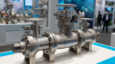
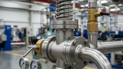
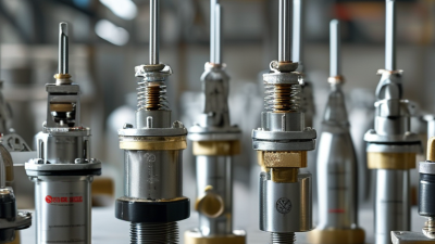
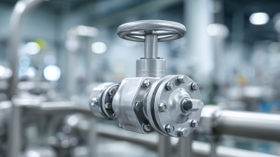
Choosing the right globe valves can determine whether a process line runs smoothly or develops costly pressure problems. In real projects, valve selection starts with the service, not the catalog photograph. Engineers usually examine fluid type, operating temperature, pressure, flow rate, and required shutoff performance. A valve handling hot condensate needs different materials from one controlling corrosive chemicals. Small details matter.
Connection size matters too.
Globe valves regulate flow effectively because their internal disc moves against the seat. This design often provides precise throttling, but it can create more pressure drop than some alternative valves. That trade-off should be calculated before approval. A stainless-steel body may suit demanding environments, while carbon steel can remain practical for compatible, less aggressive services. Seat materials, actuator force, maintenance access, and installation direction also deserve careful review.
Specifications should be checked against recognized requirements, such as applicable ASME, API, or ISO standards. However, compliance marks alone do not guarantee a suitable installation. I have seen projects focus heavily on purchase price, then underestimate actuator sizing or replacement access. That approach can weaken long-term reliability. Manufacturer data, inspection records, pressure-testing evidence, and service history offer stronger confidence. No single globe valve fits every project. Sometimes, the initial selection will need revision after reviewing piping calculations or site conditions. That is not failure; it is responsible engineering. A careful comparison of performance, lifecycle cost, materials, and supplier support can protect both the process and the people operating it.
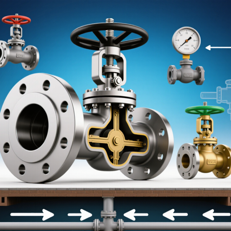
How to Choose the Right Globe Valves for Your Project?
Globe valves regulate flow by moving a disc toward or away from a stationary seat. This linear motion allows careful adjustments, even when a system needs frequent throttling. Picture a technician turning the handwheel a quarter turn to steady a fluctuating cooling-water line. That control comes with a trade-off: globe valves often create more pressure drop than gate valves. Keep that in mind when energy use matters.
Body design affects how fluid moves through the valve. A T-pattern design is common, while angle-pattern bodies turn the flow path and can simplify piping at a corner. Y-pattern designs offer a straighter route through the body. The differences are practical. Not always obvious. Check the available space, expected flow direction, and maintenance access before settling on a design.
Globe valves suit steam lines, cooling systems, and process piping where operators need reliable flow control. Selection should account for fluid type, operating pressure and temperature, required flow rate, and valve materials. A valve sized only to match the pipe may perform poorly; flow conditions matter too. Review pressure-drop data and trim options with a qualified engineer. Real systems can be untidy, and a neat specification sheet may not capture every operating change.
| Valve Design | Flow Path and Construction | Control Function | Common Applications | Key Selection Checks |
|---|---|---|---|---|
| T-pattern (standard pattern) | The flow changes direction through the body, creating a more tortuous path than in many straight-through valve designs. The disc moves toward or away from a stationary seat. | Suitable for throttling and frequent flow adjustment. Globe valves are linear-motion valves; disc position regulates the opening between the disc and seat. | Steam lines, water systems, fuel-oil services, and process lines where flow regulation or shutoff is required. | Allow for pressure loss through the valve. Check the required flow rate, pressure and temperature, materials, end connections, and actuator needs. |
| Y-pattern | The stem and seat are arranged at an angle to the main flow path. This layout can provide a less restrictive path than a conventional T-pattern design, depending on the valve design and operating conditions. | Provides throttling and shutoff while offering an alternative body layout for services where reducing flow-path resistance is important. | High-pressure or high-temperature piping and services where a conventional globe valve’s pressure loss may be a concern. | Compare the manufacturer’s flow coefficient and pressure-drop data at the actual operating point; the Y-pattern does not eliminate pressure loss. |
| Angle-pattern | The inlet and outlet are typically arranged at approximately 90 degrees, so the valve changes the flow direction within the body. | Can regulate flow and may replace a separate elbow in a suitable piping layout. | Piping layouts requiring a directional change, including some drain, vent, and process services. | Confirm that the valve’s flow direction, orientation, piping loads, and installation space suit the system. Evaluate pressure loss for the selected configuration. |
| Bellows-sealed globe valve | Uses a flexible metal bellows around the stem to provide a secondary pressure boundary and reduce leakage along the stem. It may use a T-, Y-, or other body pattern. | Provides globe-valve throttling or shutoff while helping limit fugitive emissions through the stem area. | Services where external stem leakage must be minimized, such as certain hazardous, toxic, or high-purity process applications. | Check bellows material compatibility, pressure and temperature limits, cycle life, and whether a packing arrangement is also specified as a backup. |
| Globe valve with soft seat | Uses a resilient seating material rather than a metal-to-metal seating interface. Soft-seat materials have defined temperature and chemical-compatibility limits. | Can provide tighter shutoff than many metal-seated arrangements when the service and seat material are suitable. Throttling suitability depends on the valve design and service. | Clean services requiring tight shutoff, where the process fluid and operating temperature are compatible with the seat material. | Verify chemical compatibility, temperature limits, pressure rating, and resistance to erosion or damage from particles. Do not assume a soft seat is suitable for every throttling duty. |
| Metal-seated globe valve | Uses metal seating surfaces designed for the specified pressure, temperature, and service conditions. | Commonly selected for throttling and shutoff where operating conditions may be unsuitable for resilient seats. | Many steam, hot-fluid, and industrial process services, subject to the valve’s rated materials and design. | Review the specified leakage class, seat materials, erosion and corrosion risks, and maintenance requirements; metal seats do not automatically mean zero leakage. |
Selection note: A globe valve is generally chosen when controllable throttling is important, but its pressure drop can be higher than that of some other valve types. Confirm sizing and performance using the actual fluid properties, flow conditions, pressure and temperature, required shutoff, materials, and applicable piping or industry standards.